
F1Plastic 3P Series
F1
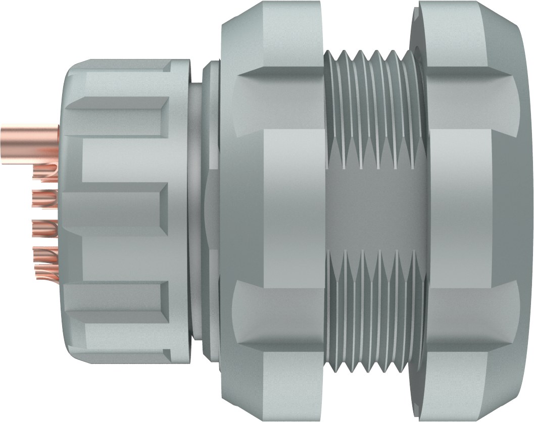
Fixed socket, front/rear panel
Connector Dimensions
Unit: mm
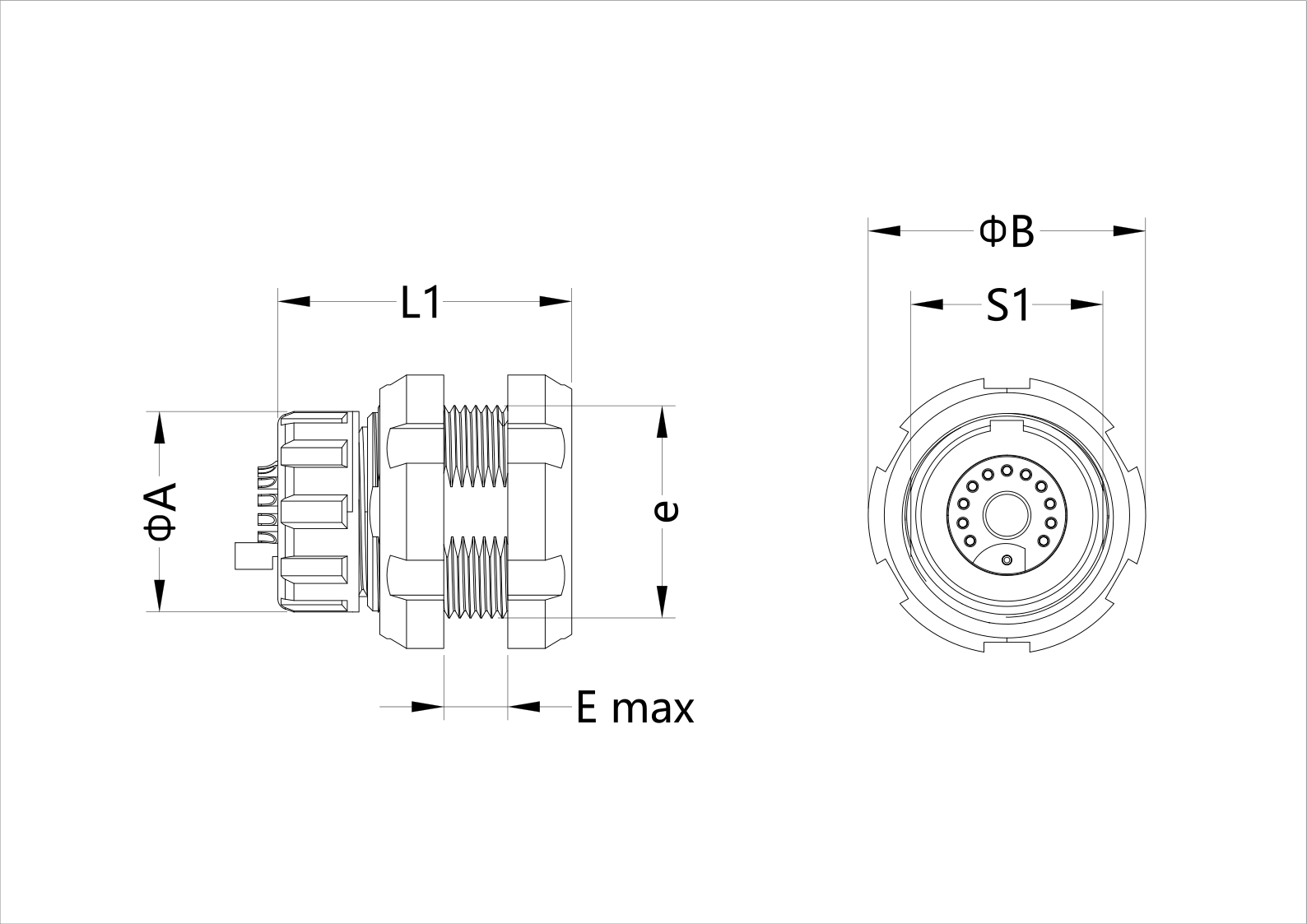
- A
- 18.8 mm
- E
- 5 mm
- e
- M20×1.0 mm
- L1
- 27.6 mm
- S1
- 18 mm
- ΦB
- 26 mm
2D Drawings · PDF
3D Drawings · STEPOn hold
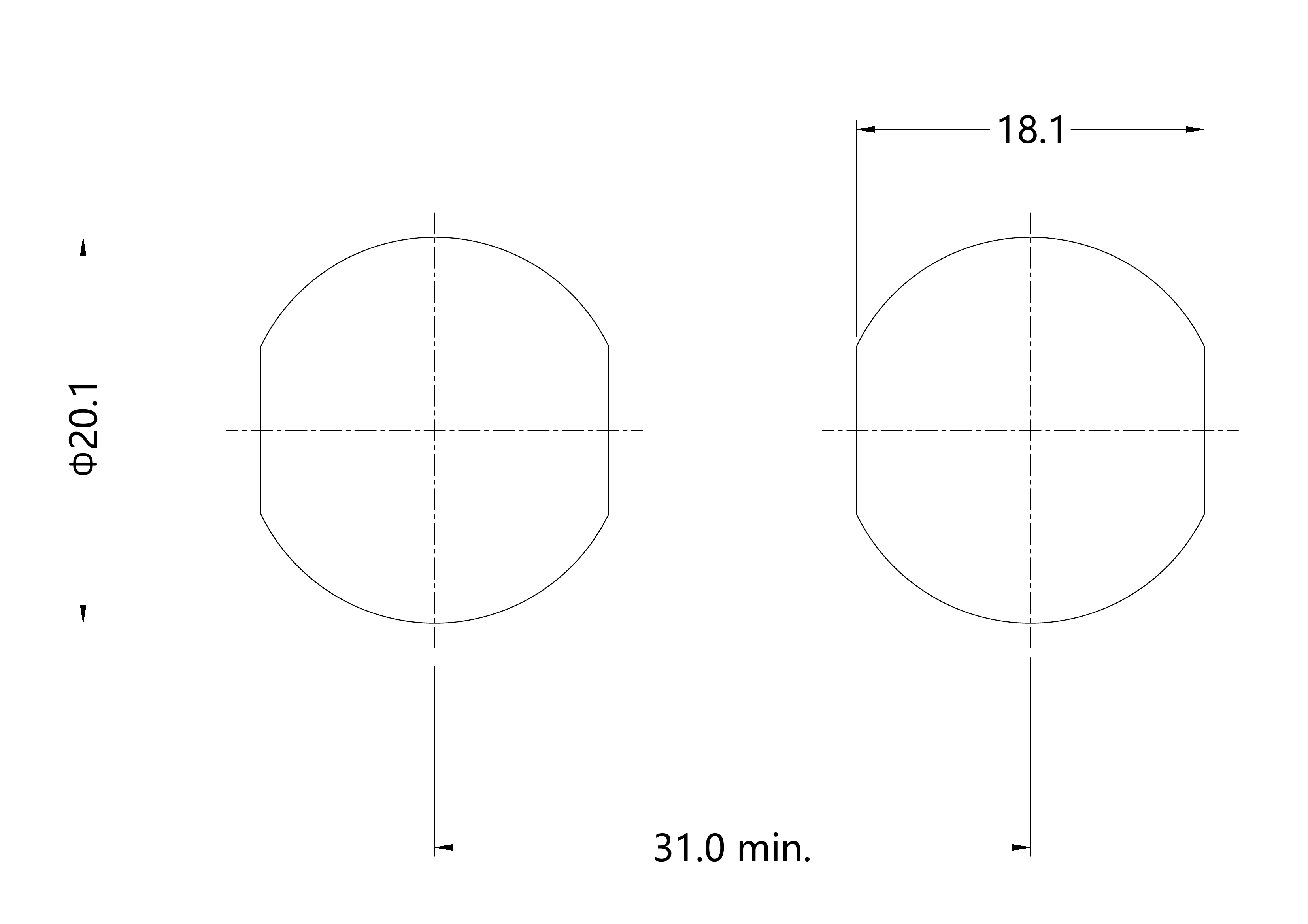
Contact us for 3D modelsPanel Cutout
Unit: mm
Click to enlarge
- A
- 20.1 mm
- B
- 18.1 mm
- L
- 31 mm
Keying Options
G
0°
Pin Configuration
| Code | Contacts | ΦA (mm) | Solder Φ (mm) | Test Voltage (KV rms) | Creepage (mm) | Rated Current (A) |
|---|---|---|---|---|---|---|
| 6+1LV | 7 | 0.9 | 0.8 | 3.9 | 1.95 | 6 |
| 10+1LV | 11 | 0.9 | 0.8 | 3.3 | 1.25 | 5 |
| 14+1LV | 15 | 0.9 | 0.8 | 1.7 | 0.9 | 4 |
| 18+1LV | 19 | 0.7 | 0.6 | 2.7 | 0.7 | 3 |
| 9+1LV+1HV | 11 | 0.9 | 0.8 | 1.7 | 0.9 | 4 |
| 9+1LV+1同轴 | 10 | 0.9 | 0.8 | 1.7 | 0.9 | 4 |
| 9+1LV+1光纤 | 10 | 0.9 | 0.8 | 1.7 | 0.9 | 4 |
| 11+1LV+1光纤 | 12 | 0.7 | 0.6 | 2.7 | 0.75 | 3 |
| 3气流体+3LV | 3 | 0.7 | — | 3 | 1.45 | 9 |
| 11+2LV+1气流体 | 13 | 0.9 | 0.6 | 2.7 | 0.75 | 3 |
Note: Depending on the application and relevant standards, more stringent working voltages may be applied. Recommended working voltage = 1/3 of test voltage.